Home » Without Label » Contrl Wiring Diagram Of Star Delta Starter - Automatic Star Delta Starter Aboutelectricity / Star delta starter three phase motor connection without timer power control wiring diagrams.
Contrl Wiring Diagram Of Star Delta Starter - Automatic Star Delta Starter Aboutelectricity / Star delta starter three phase motor connection without timer power control wiring diagrams.
Contrl Wiring Diagram Of Star Delta Starter - Automatic Star Delta Starter Aboutelectricity / Star delta starter three phase motor connection without timer power control wiring diagrams.. In star delta starting an induction motor is connected i. Control wiring diagram of star delta starter free. When the fault occurs the thermal overload relay will trip the circuit. Star delta starter three phase motor connection without timer power control wiring diagrams. Most induction motors are started directly on line, but when very large motors are started that way, they cause a disturbance of voltage on the supply lines due to large starting curr…
Two methods used for reduction of starting voltage are: Power and #control circuit.star delta starter control circuit #diagram star delta control circuit s. Drawings explained step by step. In the above star delta starter control circuit wiring diagram with timer and normally close push buttonnormally open push button switch. The following section of plc tutorial will explain the ladder programming for star delta motor starter.
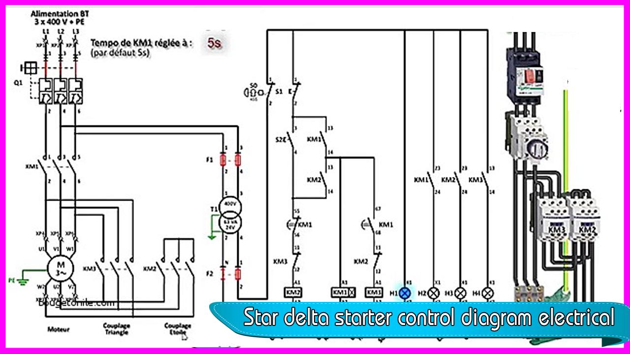
Star Delta Starter Control Diagram Electrical For Android Apk Download from image.winudf.com Star delta starter wiring diagram 3 phase with timer ecclesbourne valley railway news feed view 20 star delta pdf mitigation of switching effects on induction motor under. A 8 pin timer is used. Star delta starters consist of a power circuit and control circuit. A star delta starter is the most commonly used method for the starting of a 3 phase induction motor. The following section of plc tutorial will explain the ladder programming for star delta motor starter. Star delta wiring diagram with timer pdf. Power and #control circuit.star delta starter control circuit #diagram star delta control circuit s. The control circuit uses to control the starter circuit such as on, off and tripping operations.
A star delta starter is the most commonly used method for the starting of a 3 phase induction motor.
How to wire star delta starter with three phase ac motors? Now, you have a total of six terminals to connect with the motor three from the output of the olr and three from the output of the delta contactor. Drawings explained step by step. Connect those all terminal with the motor as shown in the above diagram. Star delta starter wiring diagram, this post is about the main wiring connection of three phase motor with star delta starter and control wiring diagram of 1 mccb circuit breaker 3 magnetic contactors 3 phase motor thermal overload relay / electronic overload relay ocr an on daily timer (8 pin timer. Two methods used for reduction of starting voltage are: Star delta starter control circuit diagram star delta connection star delta starter Connect a thermal overload relay with the main contactor as shown in the above diagram. Most induction motors are started directly on line, but when very large motors are started that way, they cause a disturbance of voltage on the supply lines due to large starting curr… As shown in the fig. One is power circuit and another one is control circuit. Star delta starters consist of a power circuit and control circuit. Next, the circuit goes through the nc terminals of the thermal over load relay.
Star delta starter wiring diagram 3 phase with timer ecclesbourne valley railway news feed view 20 star delta pdf mitigation of switching effects on induction motor under. Power and #control circuit.star delta starter control circuit #diagram star delta control circuit s. When the fault occurs the thermal overload relay will trip the circuit. Connect those all terminal with the motor as shown in the above diagram. 15 star delta starter control circuit diagram.
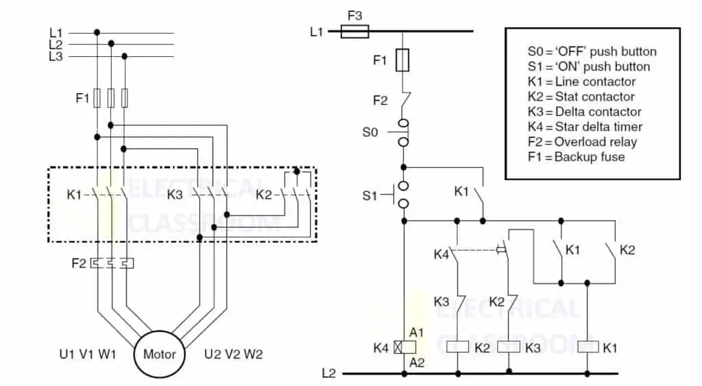
Star Delta Wiring Diagram Manual from i0.wp.com In the above star delta starter control circuit wiring diagram with timer and normally close push button/normally open push button switch. The motor terminal connection in the case of star and delta is shown in the above figure where u1 v1 w1 is the start terminal of each winding and u2 v2 w2 is the finish of each winding. If you want to find the other picture or article about motor control panel. Connect a thermal overload relay with the main contactor as shown in the above diagram. More electrical tips and diagrams www.aboutelectricit. Power and #control circuit.star delta starter control circuit #diagram star delta control circuit s. Star delta wiring diagram with timer pdf. Star delta starter diagram with connection of 3 phase motor and control circuit wiring.
Star delta starter three phase motor connection without timer power control wiring diagrams.
The on delay timer diagram is also shown in the diagram. In the above star delta starter control circuit wiring diagram with timer and normally close push button/normally open push button switch. As you see in the above star delta starter diagram, first, an nc push button switch is connected to stop the operation. The motor terminal connection in the case of star and delta is shown in the above figure where u1 v1 w1 is the start terminal of each winding and u2 v2 w2 is the finish of each winding. Star delta starter circuit diagram. Star delta starters consist of a power circuit and control circuit. If the motor is too heavily loaded, there will not for star delta starter circuit diagram,wiring technique and motor base termination,please read my post for star delta… When the fault occurs the thermal overload relay will trip the circuit. To limit the starting current surge, large induction motors are started at reduced voltage and then have full supply voltage reconnected when they run up to near rotated speed. 15 star delta starter control circuit diagram. One is power circuit and another one is control circuit. As shown in the fig. Dosto aaj ki is video me aap dekheenge star delta starter control circuit diagram or kaise kaam karta hai #stardeltastartercircuitsubscribe yk electrical for.
The on delay timer diagram is also shown in the diagram. Star delta wiring diagram with timer are listed below. Control wiring diagram of star delta starter free. Drawings explained step by step. One is power circuit and another one is control circuit.
Star Delta Starter Wye Delta Starters Circuit Working from www.electricalclassroom.com Star delta connection circuit diagram: More electrical tips and diagrams www.aboutelectricit. As shown in the fig. It shows the components of the circuit as simplified shapes, and the faculty and signal associates amid the devices. This energized star contactor coil and motor get connected in star. And also i will explain this starter connection step by ste. R , y, b = red, yellow, blue ( 3 phase lines)c.b = general circuit breakermain = mai supplyy = starδ = deltac1, c2, c3 = contatcors (power diagram)o/l = over load relayno = normally opennc = normally closed k1 = contactor (contactor coil) k1/no = contactor holding coil. Control wiring diagram of star delta starter free.
And also i will explain this starter connection step by ste.
In the control wiring diagram, all magnetic contactors coils are rated 220 vac. Wye delta starter control circuit diagram somurich com delta loop current a conversion chart note. Most induction motors are started directly on line, but when very large motors are started that way, they cause a disturbance of voltage on the supply lines due to large starting curr… If you want to find the other picture or article about motor control panel. As shown in the fig. Connect a thermal overload relay with the main contactor as shown in the above diagram. How to wire star delta starter with three phase ac motors? Control wiring diagram of star delta starter free. Connect those all terminal with the motor as shown in the above diagram. R , y, b = red, yellow, blue ( 3 phase lines)c.b = general circuit breakermain = mai supplyy = starδ = deltac1, c2, c3 = contatcors (power diagram)o/l = over load relayno = normally opennc = normally closed k1 = contactor (contactor coil) k1/no = contactor holding coil. As you see in the above star delta starter diagram, first, an nc push button switch is connected to stop the operation. Star delta starter control circuit diagram star delta connection star delta starter Star delta starter circuit diagram.